• facebook

Biodiesel & Black Diesel Dictionary

Below, you’ll discover commonly used definitions and terms within the oil burner and biodiesel community. Familiarizing yourself with these terms is important when processing and producing waste oil. The provided definitions cover various aspects of the biodiesel process, including acronyms and chemicals utilized in biodiesel production. In addition, it covers terms and acronyms used when processing Waste Oils or Black Diesel. 

ASTM: The organization that sets international standards for a variety of materials. The specification for biodiesel is ASTM D6751. Renewable diesel falls under ASTM D975, the diesel specification.

Autoignition: Autoignition is the spontaneous ignition of a substance, such as biodiesel, without an external ignition source. Understanding the autoignition temperature is crucial for safe handling and storage.

B20: B20 refers to a blend of 20% biodiesel and 80% diesel fuel. It is a common biodiesel blend used in various diesel engines.

B5, B10, B20: A fuel that is a blend of biodiesel and petroleum diesel is commonly abbreviated to a “B” and then the percentage of biodiesel in that fuel. B20, for example, is 20 percent biodiesel and 80 percent petroleum.

Biodiesel: A cleaner-burning alternative to petroleum diesel that is made from renewable resources that would otherwise have no further use, including recycled cooking oil, waste animal fats, and vegetable oils.

Biodiesel: Biodiesel is a renewable fuel derived from organic materials such as waste vegetable oil or animal fats through a process called transesterification.

Brake Fluid: Brake fluid, specifically Dot 3 fluid, is cautioned against in backyard biodiesel production due to its harmful nature. It should not be used as a feedstock.

BTUs: BTUs (British Thermal Units) measure the energy content of fuels. Understanding the BTU value helps assess the efficiency of a fuel source.

Cetane number: A measure of a fuel’s combustion speed and a common indicator of fuel quality. The higher the Cetane number, the shorter the ignition time. Biodiesel and renewable diesel have a higher Cetane number than petroleum diesel.

Cloud Point: The temperature at which wax crystals cause fuel to appear cloudy. The higher the Cloud Point, the sooner the fuel starts to gel. It is one way to measure cold weather performance.

Distillation: The process of purifying a liquid using evaporation and condensation. Distillation is one of the ways biodiesel is purified, and distilled biodiesel has several benefits, including superior cold-weather performance.

Emulsification: Emulsification is the process of mixing two immiscible liquids, like water and oil. In biodiesel production, avoiding emulsification is crucial to prevent water contamination

Emulsified Oil: Emulsified oil results from the mixing of oil and water, which can complicate the biodiesel production process. Proper separation is necessary for quality fuel.

Ethanol: Ethanol is an alcohol that can be used in biodiesel production. It reacts with triglycerides in the transesterification process.

Ethylene Glycol: Ethylene glycol is a substance to be avoided in biodiesel production as it can be harmful. It is commonly found in antifreeze.

Fatty acid methyl esters: The chemical name for biodiesel, often abbreviated as FAME. A FAME molecule is comprised of a fatty acid and an alcohol.

Feedstock: The raw material used to create fuel. For biodiesel and renewable diesel, these are renewable resources such as recycled cooking oil, vegetable oils, and waste animal fats.

Flash Point: The flash point is the lowest temperature at which a substance vaporizes to form an ignitable mixture. It’s a safety consideration in handling biodiesel.

FPHE: FPHE stands for flat plate heat exchanger, a device used to transfer heat efficiently in biodiesel production processes.

Glycerin: Glycerin, or glycerol, is a byproduct of the transesterification process in biodiesel production. Proper disposal or utilization is essential.

Gravity Fed Centrifuge: A gravity-fed centrifuge is a direct-drive centrifuge with the motor directly coupled to the rotor. It facilitates the separation of impurities from biodiesel.

Greenhouse gases: Gases, such as carbon dioxide, that trap heat in the atmosphere, contributing to global warming.

Hydrocarbons: An organic compound containing carbon and hydrogen. In the presence of nitrogen oxides (NOx) and sunlight, unburned hydrocarbons create ground-level ozone, which harms lungs and creates urban smog.

Lubricity The ability of a lubricant to reduce friction and prevent wear in an engine. Ultra-low sulfur diesel has very little lubricity, whereas biodiesel has great lubricating characteristics.

Methanol: Methanol is a key component in the transesterification process of biodiesel production. It reacts with triglycerides to form biodiesel.

Neat biodiesel: Biodiesel that has not been blended with another fuel. It is 100 percent biodiesel and is also called B100.

Particulate matter: Particulates — including solids and liquid droplets— from exhaust systems harm the climate and human health. Fine particles can penetrate deep into a person’s lungs and even enter the bloodstream.

pH Testing: pH testing involves measuring the acidity or alkalinity of biodiesel. It ensures the fuel falls within acceptable ranges for engine compatibility.

Pressure Centrifuge: A pressure centrifuge is a centrifuge that spins from oil pressure escaping the rotor, aiding in the separation of impurities from biodiesel.

Regular Unleaded Gasoline (RUG): RUG refers to regular unleaded gasoline, a type of fuel that should be avoided in the production of biodiesel due to its different chemical composition.

Renewable diesel: A renewable fuel that is chemically similar to petroleum diesel but with much lower emissions. It is made from the same feedstocks as biodiesel but has a different production process and meets a different specification.

Settling: Settling involves allowing oil to sit so that water and oil separate, and debris drops out of the oil. It is a crucial step in biodiesel production.

SVO: SVO stands for Straight Vegetable Oil, which can be used as a feedstock in biodiesel production.

Transesterification: A chemical process in which feedstock is reacted with an alcohol (typically methanol) to make biodiesel.

ULSD: ULSD stands for ultra low sulfur diesel, a type of diesel fuel with reduced sulfur content.

W80: W80 is a fuel blend consisting of 80% waste oil and 20% regular unleaded gasoline.

W90: W90 is a fuel blend consisting of 90% waste oil and 10% regular unleaded gasoline.

Wash Process: The wash process is a step in biodiesel production that involves removing impurities, catalyst residues, and glycerol from the biodiesel.

Waste Motor Oil (WMO): WMO is used lubricating oil that can be recycled and potentially used in the production of black diesel.

Waste Vegetable Oil (WVO): WVO is a discarded cooking oil, often used as a feedstock in biodiesel production.

WATF: WATF stands for Waste Automatic Transmission Fluid, which can be considered as a feedstock in biodiesel production. WATF is one of the best oil sources that can be used as a fuel because of its viscosity and detergent properties.
UFC Motor Replacement 

1. Bowl Removal

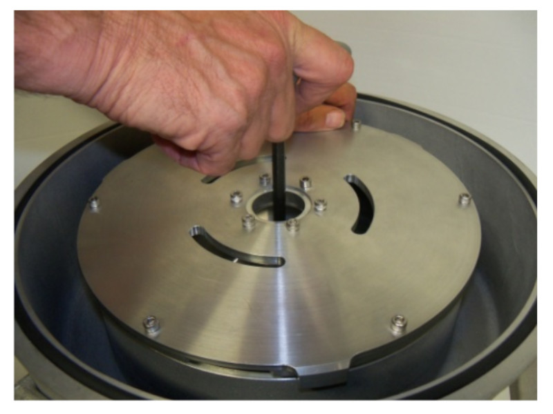
Using an 8 mm Allen wrench, secure the bowl and loosen the nut by turning it counterclockwise. Gently pull the bowl out of the housing and place it in a container to collect any residual oil.

bowl remove

2. Bowl Mount Removal

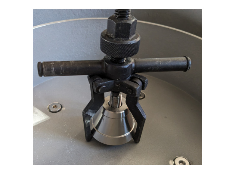
Utilize a gear puller obtained from an auto parts store. Attach the three hooks to the bottom of the bowl mount. Hand-tighten the gear puller, then use a wrench for further tightening to safely remove the mount from the motor shaft. Ensure the force is applied to the motor shaft, not the housing, allowing the mount to slide off smoothly.

Bowl Mount Removal

3. Motor Removal

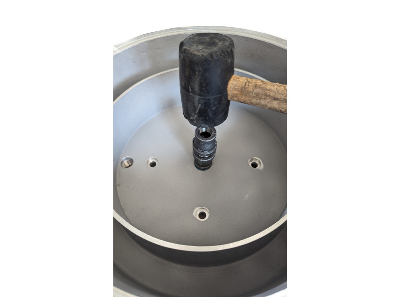
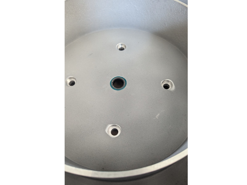
Using a 4mm Allen wrench, remove the three legs of the Ultimate Force Centrifuge, placing the motor base on the ground. This will aid in removing the motor from the unit. Using a 3/16 Allen head screwdriver, remove the 4 bolts securing the motor. Set them aside in a safe location, not damaging the sealed washers if reusing. Remove the housing by lifting up from the motor. Flip the housing upside down and, with a mallet and socket, gently tap out the old seal.

4. Install New SKF Seal

Lightly coat the Ultimate Force Centrifuge Housing with silicone or grease to facilitate seal installation. Verify the coil spring inside the SKF seal is properly seated. Use a socket or pipe fitting of similar size to tap the motor shaft seal into place carefully. Avoid overdriving the seal to prevent compromise or damage.

Install New SKF Seal
Install New SKF Seal 2

5. Install The Motor

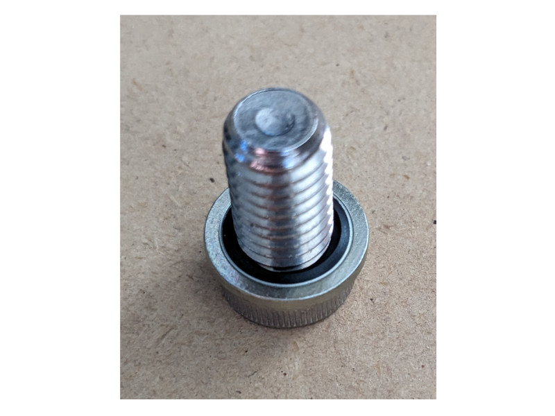
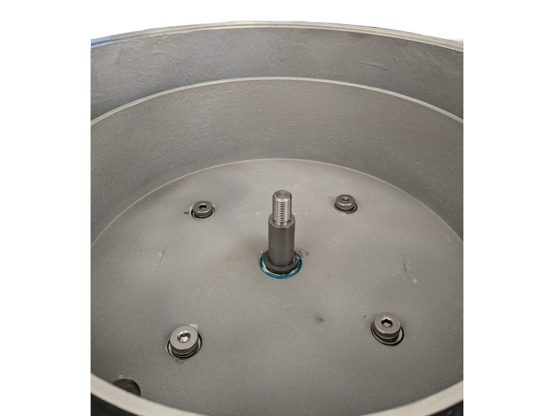
Place the motor on a stable surface, lubricate the motor shaft with grease, and slide the housing onto the motor shaft, ensuring not to damage the rubber seal. Use the sealed washers from our reseal kit on the 4 housing bolts and securely tighten them into the motor.

Install The Motor
Install The Motor 2

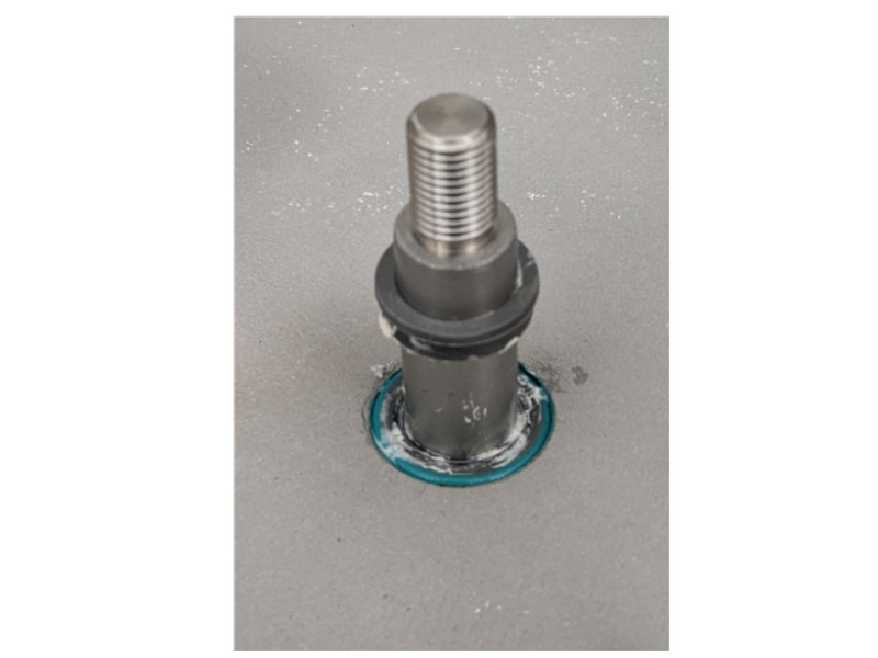
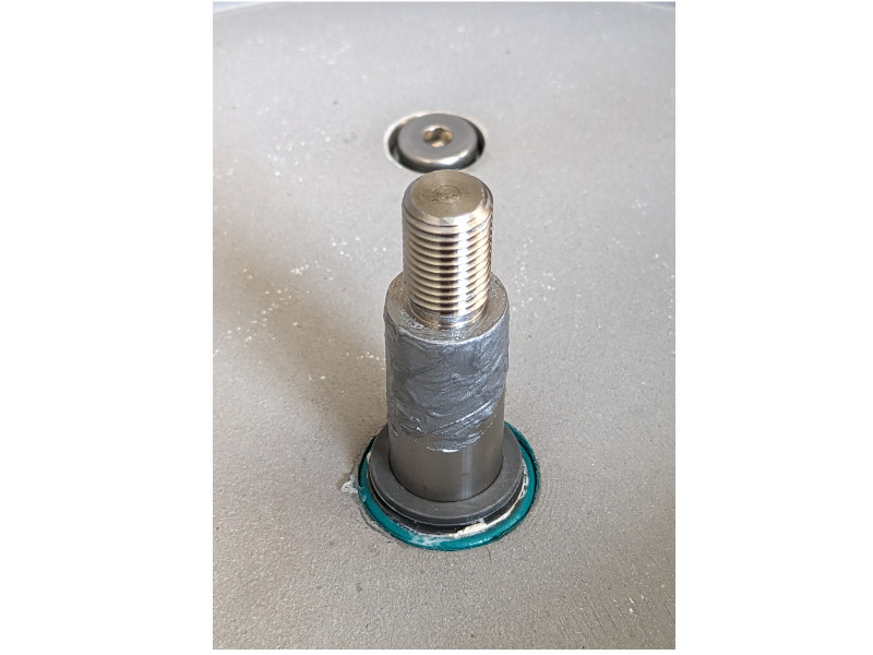
6. Install V-Seal and Apply Anti-Seize

Slide the V-seal down the motor shaft, pushing it firmly into the motor shaft seal with the V portion facing down to prevent leaks. Apply a thin layer of antifreeze onto the motor shaft for easier future installation and removal of the bowl mount.

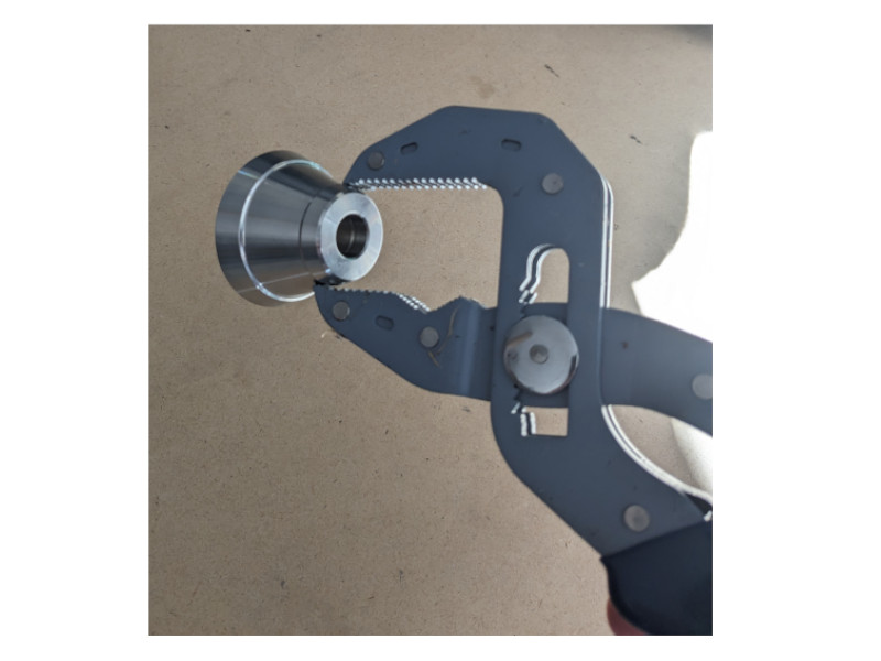
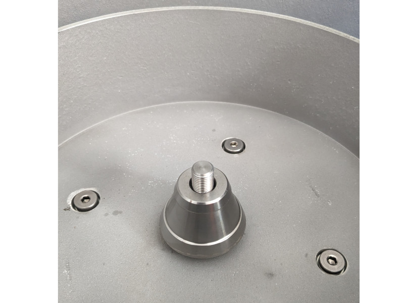
7. Install Bowl Mount

Heat the bowl mount in boiling water for 5 to 10 minutes. Using pliers, carefully pick up the bowl mount and quickly slide it onto the shaft, avoiding burns or drops. Ensure the bowl mount is fully seated by the groove, catching the motor shaft lip. Allow the bowl mount to cool for 5 minutes; if not fully seated, repeat the process.

Install Bowl Mount
Install Bowl Mount 2

8. Attach Bowl to oil centrifuge unit

Place the bowl into the housing and onto the motor shaft. Hold the bowl steady with an 8 mm Allen wrench and turn clockwise to tighten the nut.

bowl attach

Ultimate Force Centrifuge: Instruction Manual

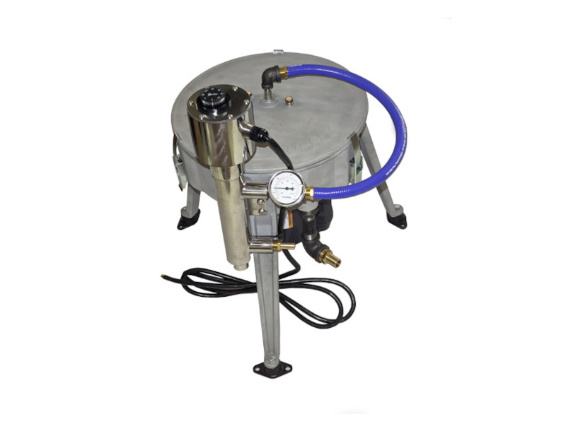
The Ultimate Force Centrifuge ships completely assembled with the exception of leg attachment, threading of fittings, and basic wiring.  If you purchased an inline heater, you will need to install it.  While every precaution has been taken to be sure your equipment arrives in perfect condition by packing with great care, handling and shipping is out of our control.  Upon its arrival, please inspect the package and report any obvious damage to us right away.

*Tools necessary:  4 mm, 5 mm, 8 mm, and 3/16” Allen wrenches 

SAFETY

As with all equipment, there are safety hazards involving oils, centrifuge use, static electricity, and piping of your unit and holding tank.

  • Never operate the centrifuge without the cover securely attached.
  • Never open a running centrifuge.
  • Caution must be taken when centrifuging all flammable liquids.
  • Ground all equipment before use to prevent static electricity.

It is the owners’ sole responsibility to decide what types of liquids are safe to centrifuge taking into consideration flammable vapors.

Unpacking 

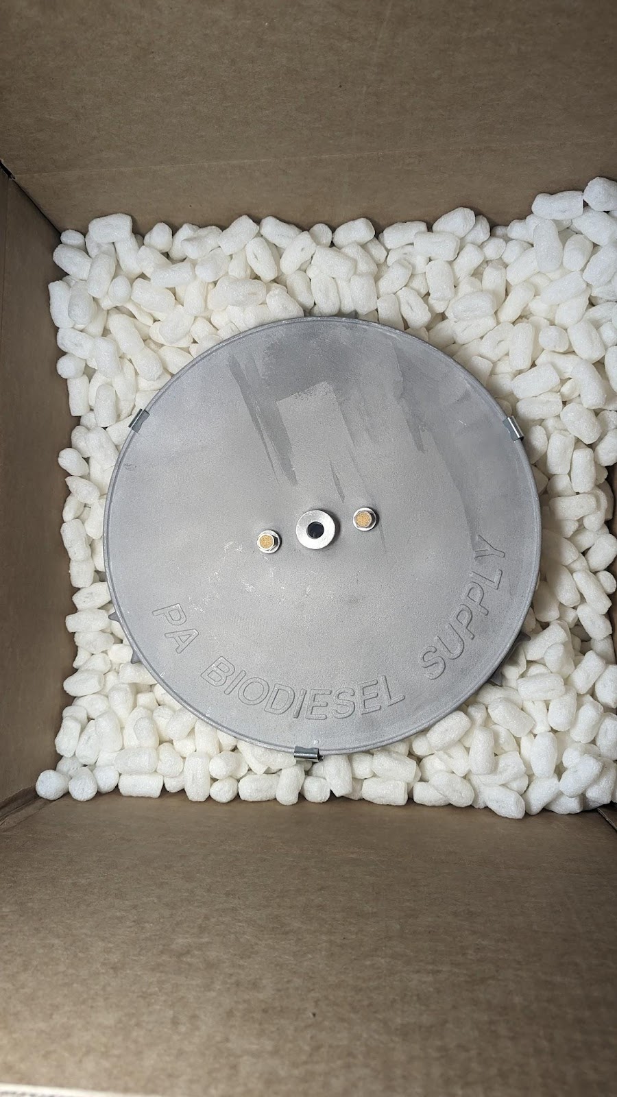
When unpacking your centrifuge pull the unit out of the box and set aside on carpet or padded area so you do not scratch the lid.  Since the unit weighs approximately 65 lbs, caution should be used when removing it from the box. The packing peanuts are biodegradable and can be recycled or disposed in a sealed bag.

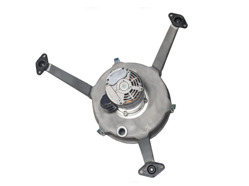
The Ultimate Force comes completely built except for the legs.  The legs are installed on the unit in reverse for ease of shipping.  Hold the top of the leg in place.  While using a 4 mm Allen wrench, remove the two screws on each leg.  Turn the legs around and reinstall.  You should be able to hold the leg in place and hand tighten both bolts.   When both bolts are in, using the Allen wrench, tighten both bolts again.  When the three legs are reversed, they will extend out from the unit as pictured.

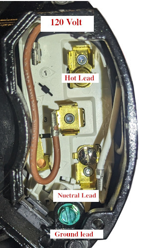
120V Wiring

Consult the Wiring Diagram on the motor 

  1. Identify the color-coded wires on the motor. The most common colors are black, white, brown, red, and green
  2. Remove the black plastic cover on the side of the motor and install the wire clamp. Run your power cord through the connector.
  3. Match the black wire on the motor to position 2 as in the photo.
  4. On your 120V cord connect the Hot lead (Typically black) to position 1.
  5. Match the white wire on the motor to position 4.
  6. The white wire on the power cord is neutral, connect it to position 4 as well.
  7. Connect the ground wire to the ground screw on the motor.
  8. Use wire connectors or wire nuts to secure the connections.
  9. Reinstall the motor cover plate.
  10. Once all connections are made, turn on the power supply and test the motor.

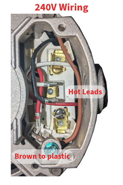
240V Wiring

  1.  The motor arrives with the three motor wires configured for 120V. The Brown, White, and Black wire will need to be disconnected.
  2. Install the wire connector onto the motor side and run your power cord through the connector.
  3. Match the Black and White wire to position 3.
  4. Connect the brown wire to position 5 or “P” which may be plastic.
  5. One of each hot wire from your power cord will be connected to a Hot Lead.
  6. Connect the ground from the power cord to the motor ground screw.
  7. Use wire connectors to install the wires to the proper position.
  8. Reinstall the motor plate cover. 
  9. Turn on the power supply to test the motor.

*Wiring may vary depending on the motor your unit has installed. Always consult the wiring diagram on the motor prior to testing.*

Setting up Attachments

Set your unit on a flat surface below the contaminated oil feed and above the container being used to catch the clean oil.  

The centrifuge comes with a vibration damper at the bottom of all three legs.  Each damper has two holes which are to be used to mount your centrifuge to a hard surface.

Recommendation:  Use a piece of plywood larger than your clean oil container.  Mount the plywood to the container ensuring that the equipment and plywood will not move.

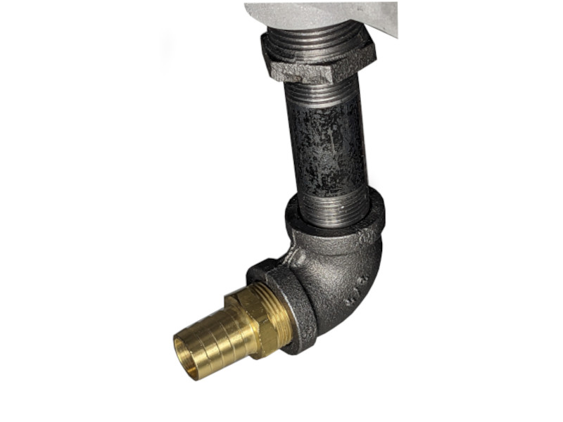
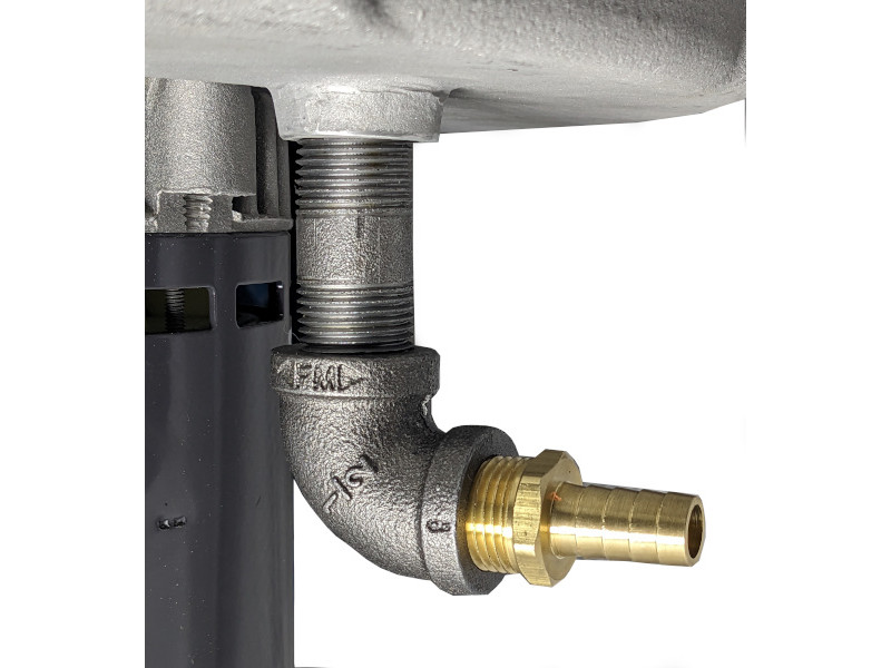
The clean oil and contaminated oil drain both come with all fittings included.  The ¾” 90 and the ½ “ 90 will need their respective hose connection fittings installed as pictured below.  You will need to purchase ¾” hose for the clean oil drain and ½” hose for the contaminated oil drain.  The length of these hoses is dependent on the distance to your container. 

Your supply container should have a gate valve to control the oil flow and a ball valve to be used as a shutoff valve.  The flow will be dependent on temperature as well as the amount of oil in the container. As the temperature of the oil decreases, its viscosity increases, resulting in a slower flow. Additionally, as the oil level decreases within the container, the flow rate will also decrease.

The clean oil drain is ¾” and needs to have fittings attached to the bottom of the centrifuge as in the picture above on the left. Clean oil will drain during operation and will cease draining upon shutdown.

The contaminant oil drain is ½”.  Connect the fittings as pictured above on the right. The ½” hose from the contaminant side will only drain when shutting down the unit or when overflowing.

Feed to Centrifuge Attachment

The centrifuge comes with a 1/2” hose barb to introduce oil into it.  Make the connections from your dirty oil container to include a gate valve for adjusting flow, a ball valve as an on/off flow valve, ending with a ½” hose barb.  Connect the two hose barbs with ½” clear braided hose.

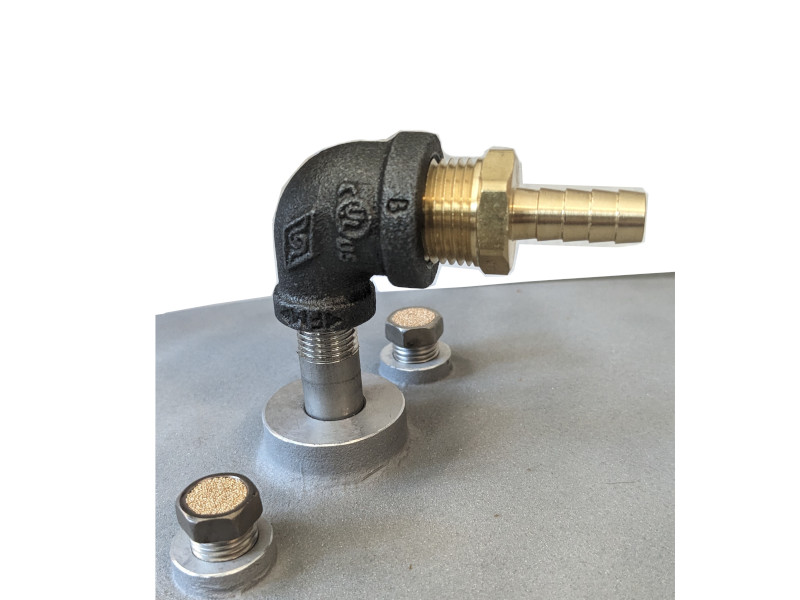
The oil entry fitting is a ½” hose barb, 90 and reduced down to a ¼” nipple.  Install the  ¼” nipple into the opening on top of the lid.  (This will be a tight fit due to o-rings in the opening.)  The lid has two breather caps for forced ventilation.

Heater Installation

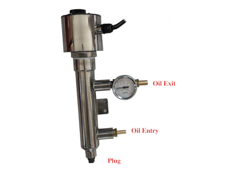
When attaching the heater to the leg, first hand tighten one bolt through the bottom hole in the leg and into housing.  Then attach the heater using the top hole.  Place bolt through the top hole in the heater and centrifuge leg and into housing, then remove bottom bolt from leg and swing heater into place aligning bottom heater hole with leg hole.  Bolt together and tighten both bolts.

From your dirty oil container, run your ½ “ hose to the bottom hose barb on the heater.  Oil should always be introduced into the bottom of the heater and exit the top ensuring the heating element is always submerged.  Connect the top hose barb with the 400 degree F. hose to the ½” hose barb on the lid of the centrifuge.  NEVER use a hose from the heater feeding the centrifuge that is not rated for heat.  Place a  ¼ “ plug in the bottom of the heater. You are now set up and ready to turn your unit on. 

NOTE:  Always turn the centrifuge on first (you want the centrifuge on before you open the oil flow), and turn the centrifuge off last (you want the centrifuge running until you turn the oil flow off).  

Finishing the Centrifuge Run

After you have turned the centrifuge off, the bowl will quit spinning and will automatically drain  out of the dirty oil drain.  Do not remove the bowl from the unit until all oil has drained out.  This can be verified by checking the dirty oil drain hose.  

Bowl Removal

With an 8 mm allen wrench, hold the bowl steady and loosen the nut.  Turn counterclockwise to loosen the nut. Pull the bowl out of the housing and place it in a container to catch any residual oil left in the bowl.

C:\Users\owner\Pictures\2013-10-13 user manual pictures\user manual pictures 001.JPG

Bowl Lid Removal

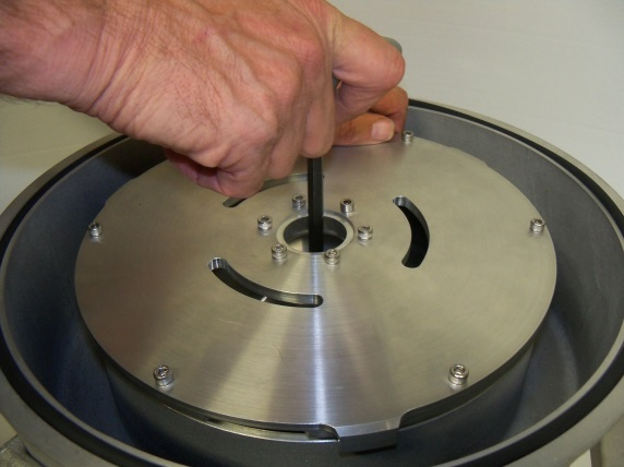
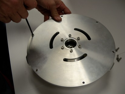
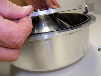
With a 4 mm Allen wrench, hold the bowl steady, loosen and remove six screws.

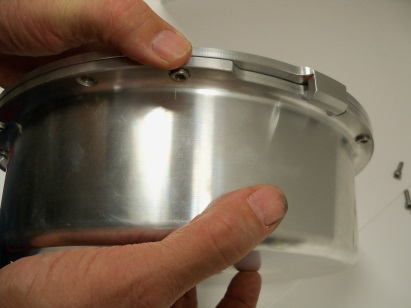
After removal of screws, lift the lid and turn counterclockwise approximately 1 ½” to release the locking lid.

The bowl does not necessarily need to be removed for each cleaning, as the bowl itself is self draining.  Once the bowl lid is removed, you can simply wipe out the bowl.

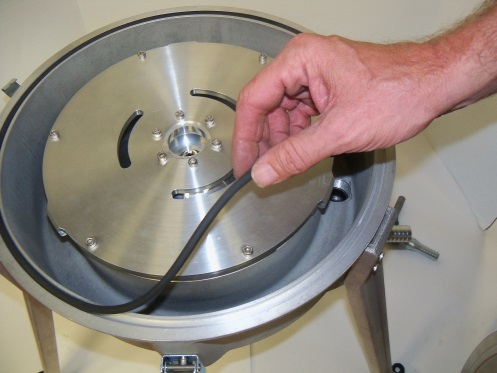
When replacing the bowl lid, ensure the seal is properly placed in the groove.  Make sure all bolts are tight.  Set bowl on bowl mount inside housing.  Holding with one hand, tighten the nut.

C:\Users\owner\Pictures\2013-10-13 user manual pictures\user manual pictures 017.JPG

Once your bowl has been installed, check all bolts on the bowl lid and the bowl mount for tightness.  Make sure the seal for the housing is in the groove and install the housing lid.  Lock down the three latches.  You are now ready to start another run.

Disclaimer:

 Every effort has been made to ensure the accuracy and completeness of the instruction manual. However, PA Biodiesel Supply, a Division of Wheeler Inspirations LLC, makes no warranties, expressed or implied, regarding errors or omissions, nor will it be held liable for the use of this product or any adapted version of this product, and assumes no legal liability nor responsibility for loss or damage resulting from use of the information contained herein.