(833)-370-7590
 info@pabiodieselsupply.com


This guide walks you through fully assembling and configuring your Ultimate Force Fuel System (UFFS) centrifuge, from unboxing to running your first batch of clean fuel. Follow the steps in order — each stage builds on the last.
P.S This Manual is still being revised and updated. Future revisions will come in the following week. If you have any feedback, please let us know.
Pre-Manual Notes & Open Items
Complete Parts & Components List
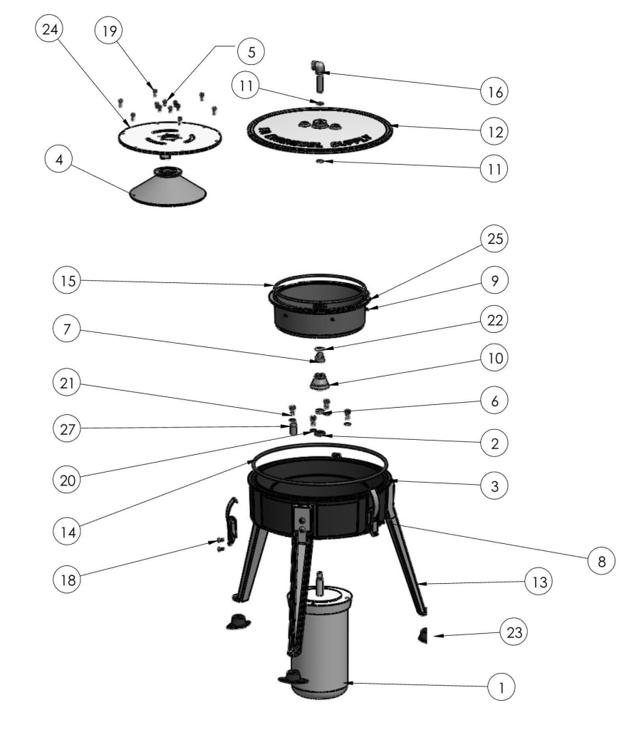
The table below is sourced from the engineering drawing B-11239-00 Rev G.
| Part Number | Description | Qty |
|---|---|---|
| 11239-01 | Motor | 1 |
| 11239-02 | SKF Oil Seal | 1 |
| 11239-03 | Housing | 1 |
| 11239-04 | Accelerator | 1 |
| 11239-05 | Screw, M5 x 10mm SHCS | 6 |
| 11239-06 | V Seal | 1 |
| 11239-07 | Nut | 1 |
| 11239-08 | Draw Latch | 3 |
| 11239-09 | Self Clinching Nut | 6 |
| 11239-10 | Bowl Mount | 1 |
| 11239-12 | O-Ring | 2 |
| 11239-14 | Housing Lid | 1 |
| 11239-15 | Leg | 3 |
| 11239-16 | O-Ring Gasket | 1 |
| 11239-17 | O-Ring | 1 |
| 11239-18 | Inlet Pipe Assembly | 1 |
| 11239-19 | Screw, M8 x 22mm Button Hd Cap Screw | 6 |
| 11239-20 | Screw, M5 x 12mm Machine | 6 |
| 11239-21 | Screw, M5 x 14mm SHCS | 6 |
| 11239-22 | Bonded Seal | 4 |
| 11239-23 | Screw, 3/8-16 x .75″ Low Head | 4 |
| 11239-24 | Retaining Ring, for 24mm Bore | 1 |
| 11239-25 | Vibration Damping Mount | 3 |
| 11239-28 | Lid | 1 |
| 11239-29 | Bowl | 1 |
| 11239-27 | Pilot for Seal Assembly (assembly tool — reference only) | 1 |
| 11239-31 | Breather Cap | 2 |
| 11239-32 | Bolt, 5/16 x 1″ | 3 |
Note: Additional items such as heater, plumbing fittings, and hose are listed separately in the kit.
Required Tools List (Customer-Supplied)
- 4 mm Allen wrench
- 5 mm Allen wrench
- 8 mm Allen wrench
- 3/16″ Allen wrench / Allen head screwdriver
- Wire connectors / wire nuts
- Power cord (120V or 240V depending on setup)
- Pliers (for handling heated bowl mount)
- Mallet and appropriately sized socket (for seal installation)
- Pot for boiling water (bowl mount heat press)
- Silicone or grease (for seal lubrication)
- Anti-seize compound (for motor shaft)
- Teflon tape (for plumbing connections)
Safety Warnings
As with all equipment, there are safety hazards involving oils, centrifuge use, static electricity, and plumbing of your unit and holding tank.
- Never operate the centrifuge without the cover securely attached.
- Never open a running centrifuge.
- Caution must be taken when centrifuging all flammable liquids.
- Ensure oil containers will hold all the oil without overflowing.
- Ground all equipment before use to prevent static electricity.
It is the owners’ sole responsibility to decide what types of liquids are safe to centrifuge, taking into consideration flammable vapors.
Part 1: Core Assembly — “Assembling the Ultimate Force”
Every customer follows Steps 1–11 in order. This is the sequential build from unboxing to a fully assembled centrifuge.
Upgrade to the 6,000 RPM Unleashed →
Step 1. Unpackaging
The Ultimate Force Fuel System arrives as a kit for you to assemble. This reduces damage in transit and keeps the shipping costs low for you.
When your package first arrives, inspect it for any damage that may have occurred during transit. If the box has been damaged or torn, please take pictures of it and notify us immediately so we can claim insurance with the courier in the event of missing or broken parts.
The packing peanuts that we use in the package are made from starch and are biodegradable. They can be recycled or thrown away in a sealed bag. Moisture and humidity will cause them to shrink and even mold if in a dark place. If you want to store them for the future, make sure they are in a dry sealed bag.
The Ultimate Force is separated into a few different assemblies based on category: your casting kit, plumbing kit, hardware kit, and motor. All of your parts have an ID label with the part number, description, and a little note of where the part is installed for quick reference.
We recommend setting the parts on carpet, or some other soft surface so that the parts do not become damaged or scratched. Concrete is the worst surface you can place it on. Use cardboard at the very minimum if working on the floor.
The Ultimate Force is heavy once fully assembled at 65 pounds. So, build it close to the area you will be setting it up.
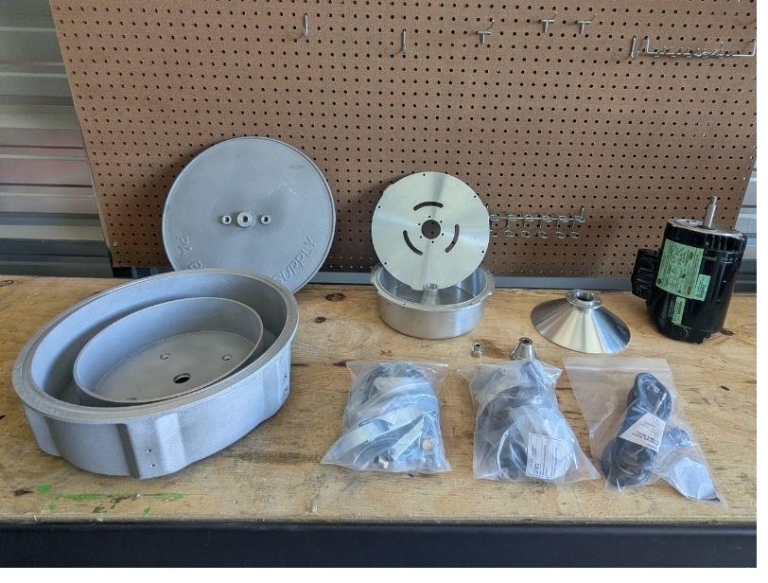
Note: Do not discard any packaging material until you have verified all parts are accounted for. Small hardware bags can easily be overlooked in packing material.
Step 2. Layout of Parts, Index List, Label IDs
As you remove the package and get it ready for assembly, group the different parts bags together so you do not misplace them. Each bag has a part label and ID that will be referenced throughout this guide as we build the Ultimate Force Fuel System.
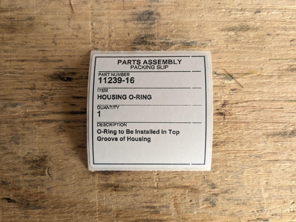
The heater kit and plumbing assemblies can be placed to the side. They will be the last part of the assembly when we connect the Ultimate Force to the dirty oil tank and the clean oil fuel tank.
The Ultimate Force is very simple to set up with only 6 sets of fasteners and hardware to assemble to the unit.
Step 3. Installing the Motor Shaft Seal + Bolting the Motor
We will begin our assembly with the housing. An SKF motor shaft seal is set into the housing with a light coat of grease or oil as a lubricant. We then use a rubber mallet and a socket of the same size and gently pound it until the seal is fully seated. Do not overdrive the seal, or you will damage the seal and the centrifuge may leak during operation. Check the bottom of the seal after installation, and check that the spring is still in place — an internal spring is inside the motor shaft seal, and it’s what seals the motor shaft so oil does not leak through. If the spring is missing, check beneath the housing or close by in case it fell out during installation.

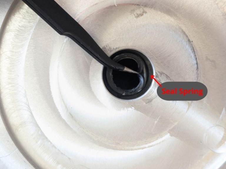
Note: Overdriving the seal will compromise it and cause oil leaks. If the seal goes in crooked, remove it and start over rather than forcing it. See Troubleshooting if you experience leaks after assembly.
Place the motor on the ground shaft up and remove the threading protector. Gently slide the housing onto the motor shaft. Make sure the lip does not catch the seal and reverse it, and make sure that the seal spring does not move or get dislodged.

(Pilot tool may not be included)
Next, take the V-seal and give it a light coat of oil or grease. Slide it onto the motor shaft with the “V” portion facing down towards the motor shaft seal.

Note: The V-seal must face V-down. If installed upside down, oil will leak past the motor shaft. This is one of the most common assembly mistakes.
The motor can now be fastened. Using the motor fastener bolt 11239-23, connect the fasteners to the 4 bonded seals 11239-22 found in the seal kit. Each bolt gets one bonded washer — these washers seal the housing from oil leaks. Apply a small amount of Lock-Tite to the bolts and Black RTV in the housing. This will prevent the bolts from backing out during operation and prevent leaks in the future.

Note: The sealed washers on the motor bolts are critical for preventing oil leaks through the bolt holes. Do not forget them or substitute standard washers. Apply RTV to the housing hole to completely seal it.
Using a 3/16” Allen head, install the fasteners and tighten them in an X pattern just like a wheel. The bolts do not have a specific torque rating; we recommend tightening them hand-tight plus a quarter turn. Be careful using an impact or you may damage the threadings — threading damage is not covered under the warranty as this is user error.
Apply a thin coat of anti-seize to the motor shaft to prepare for installation of the bowl mount.
Step 4. Wiring the Basic Motor (3,600 RPM)
The Ultimate Force basic comes standard with a 1/3 HP single-phase motor. It is rated at 744 watts and is compatible with both 50 Hz and 60 Hz power, so it will run on standard household and shop circuits. At 60 Hz, the motor runs at its standard speed of 3,450 RPM.
The motor does not come equipped with an on/off switch. For safe and convenient operation, we recommend plugging it into an outlet that is controlled by a switch like a kitchen garbage disposal, or installing an inline switch at the outlet. This gives you a simple, accessible way to start and stop the centrifuge without having to unplug it after every run.
The motor can be wired for either 120V or 240V — choose the configuration that matches your available power supply and follow the diagram on your motor.
If you are setting up the Ultimate Force Unleashed, your motor is three-phase and is wired through a Variable Frequency Drive (VFD). Skip this section and follow the Unleashed VFD wiring and programming instructions further down this guide.
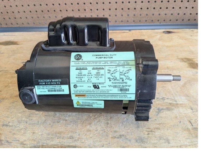
Note: Motor wiring diagrams may vary slightly between production runs. The diagram on YOUR motor is the final authority. If your wires don’t match these instructions, follow the motor’s diagram.
120V Wiring
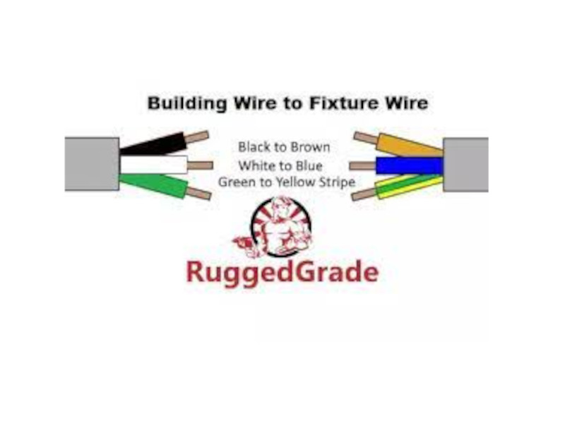
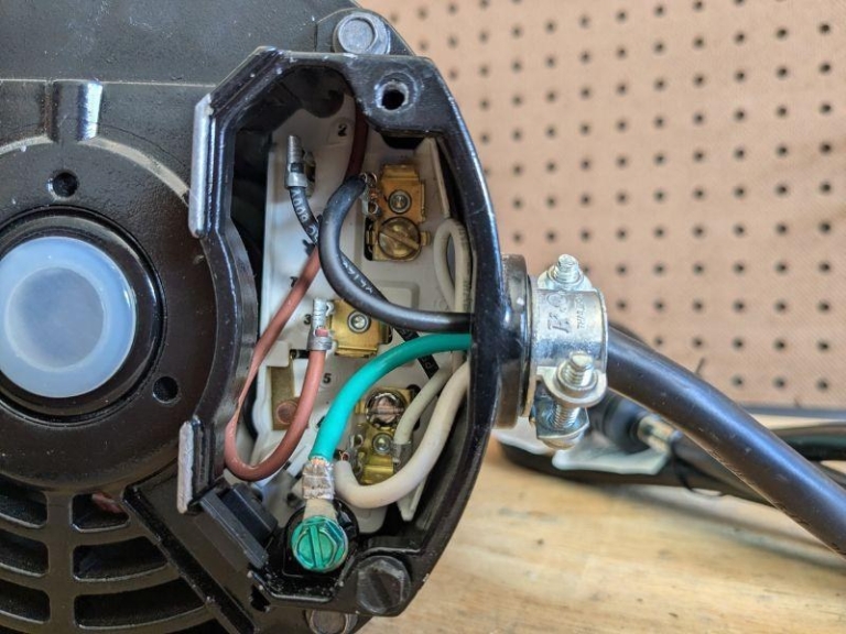
The motor arrives with its wires configured for 120V, but you should verify this before connecting power. The three motor wires are black, brown, and white. Install the wire clamp connector onto the motor side and run your power cord through it, then make the following connections to a cord:
- Match the motor’s black wire to position 2 as shown on the diagram.
- Connect the hot lead from your 120V cord (typically black) to position 1.
- Match the motor’s white wire to position 4.
- Connect the power cord’s neutral (white) to position 4.
- Connect the brown wire to position 3.
- Run the ground wire to the ground screw on the motor.
Secure each connection with wire connectors or wire nuts, then reinstall the motor cover plate. Once all of your power connections are made, turn on the power supply and test the motor.
240V Wiring
The motor arrives with its three wires configured for 120V, so the brown, white, and black wires will need to be disconnected. Install the wire connector onto the motor side and run your power cord through the connector, then make the following connections:
- Match the black and white wire to position 3.
- Connect the brown wire to position “P”, a plastic clip or connection.
- Connect one of each hot wire from your power cord to positions 1 and 4.
- Connect the neutral and/or ground from the power cord to the motor ground screw.
Use wire connectors to install each wire in its proper position, then reinstall the motor plate cover. Turn on the power supply to test the motor.
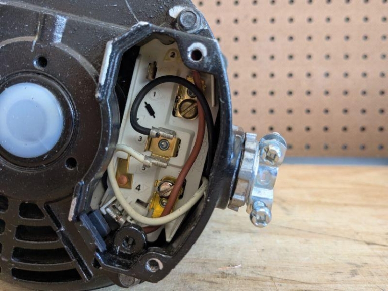

Note: If the motor does not spin or hums without turning, disconnect power immediately. Double-check all wiring connections against the motor diagram. Incorrect wiring can damage the motor.
The Ultimate Force basic motor you just wired spins at 3,450 RPM and produces 1,650 G-force. The enclosed bowl design allows the centrifuge to remove sludge and debris down to 0.5 microns. The Unleashed upgrade motor spins at 5,000 RPM and generates 4,950 G-force — a 40% increase in RPM produces 3x the G-force. Higher G-force means cleaner waste oil for your diesel engine and fewer passes needed. This is highly recommended for the enthusiast producing 100+ gallons a month or the diesel owner with a common-rail engine.
Step 5. Installing the Heat Press Bowl Mount
The bowl mount 11239-10 is an interference fitting, which means that it is heated for installation. When the part is placed onto the motor shaft and cools, it shrinks, creating a tight mechanical connection.
Heat the bowl mount in boiling water for 5 to 10 minutes. Using pliers, carefully pick up the bowl mount and quickly slide it onto the shaft. Ensure the bowl mount is fully seated by the groove catching the motor shaft lip. Allow the bowl mount to cool for 10 minutes; if not fully seated, remove the bowl mount with a gear puller and repeat the process.

Note: If the bowl mount is not fully seated, the bowl will wobble during operation causing excessive vibration. Re-boil for the full 10 minutes and try again. Do not attempt to force it with a hammer.
Step 6. Assembling the Bowl
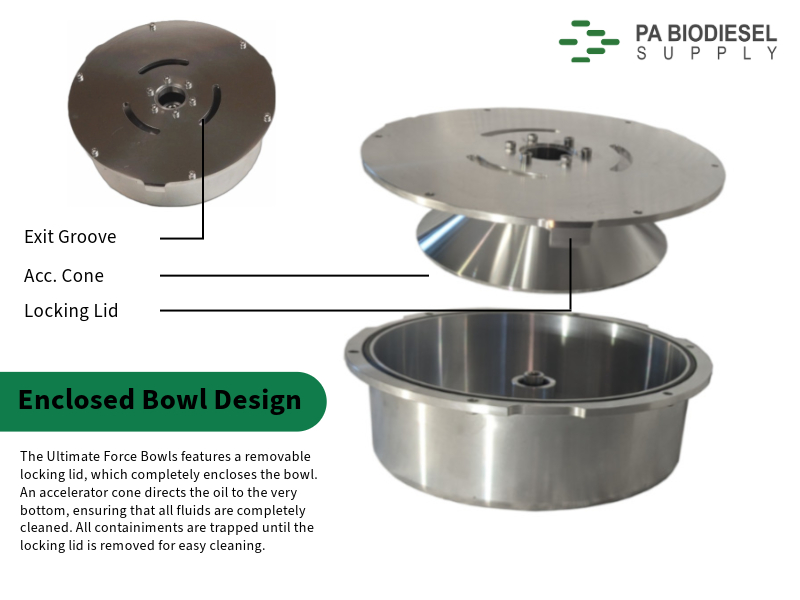
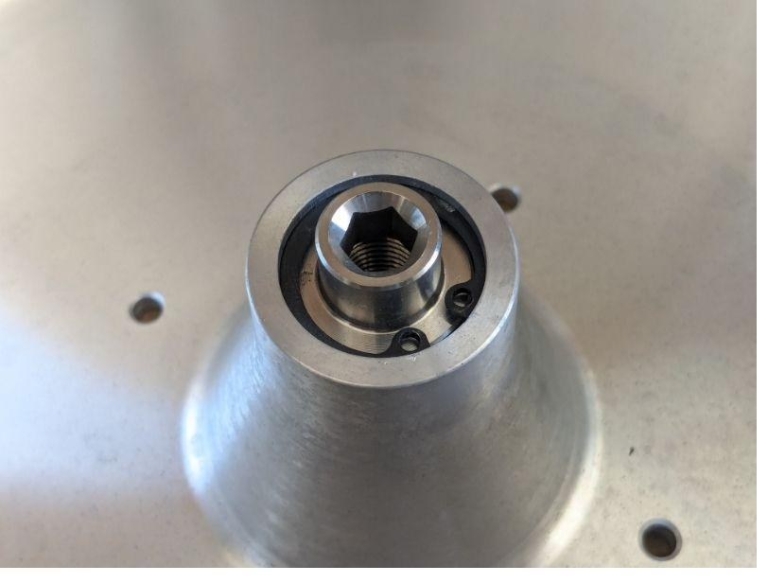
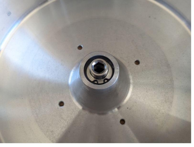
The centrifuge bowl 11239-29 is assembled from 4 machined pieces. To assemble the bowl, begin by placing the bowl nut 11239-07 into the center of the bowl. Use a pair of needle nose pliers to install the locking ring 11239-24 above the nut. The ring is fully installed when it locks into the groove — the tips of the pliers or a punch can be used to tap it into place if it is not fully seated.
Assembling the lid, you will start with the accelerator cone 11239-04. Place the locking lid 11239-28 onto the cone and line up the fastener holes. Using fastener 11239-05, install the 6 fasteners with a 4mm Allen wrench. Do not use an impact. Tighten the fasteners in a criss-cross pattern so everything remains properly seated and level. Lock-tite is optional but recommended.

Place the bowl o-ring 11239-17 in the groove of the bowl. You may now place the locking lid onto the bowl. Don’t forget to install bowl liners so that cleaning is easy in the future.
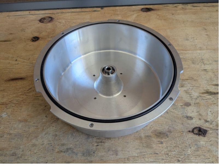
Turn the locking lid counter-clockwise 1.5” until the holes line up and then install 11239-21 fasteners in a criss-cross pattern. Do not use an impact — the screws are fastened into a steel press nut, and over-torquing these fasteners will result in the steel press nuts coming loose.

Sometimes a fastener is not able to perfectly line up with the steel press nut. The press nuts are installed by hand, and sometimes they are not perfectly level during installation. There is a simple but delicate fix to align the press nut, which will save you time and get you in operation faster so you don’t have to wait for a replacement bowl.
Screw the fastener into the nut enough that the threads catch but will not strip. You may have to remove the locking lid in order for it to thread. Using a rubber mallet, gently tap the screw into an upright position so it is level.

You can then reinstall the lid and connect all of the fasteners.
Note: Do not use an impact driver or over-tighten the lid screws. Over-torquing will break the steel nut that the screw threads into. Hand-tight with an Allen wrench is sufficient.
Step 7. Installing the Bowl to Centrifuge
Take the entire bowl assembly and place it onto the bowl mount in the centrifuge housing. Take care not to drop the bowl, or it will become damaged and need replacement. An 8mm Allen is then used to tighten the bowl nut to the motor shaft. Hold one side of the bowl so it does not spin, and tighten the nut with your other hand. The nut should be tight. Make sure that the bowl is level and you are not putting weight to one side of the bowl as it is tightened — this will cause it to be unlevel and unbalanced during operation. Give it a light spin by hand to make sure everything spins smoothly.
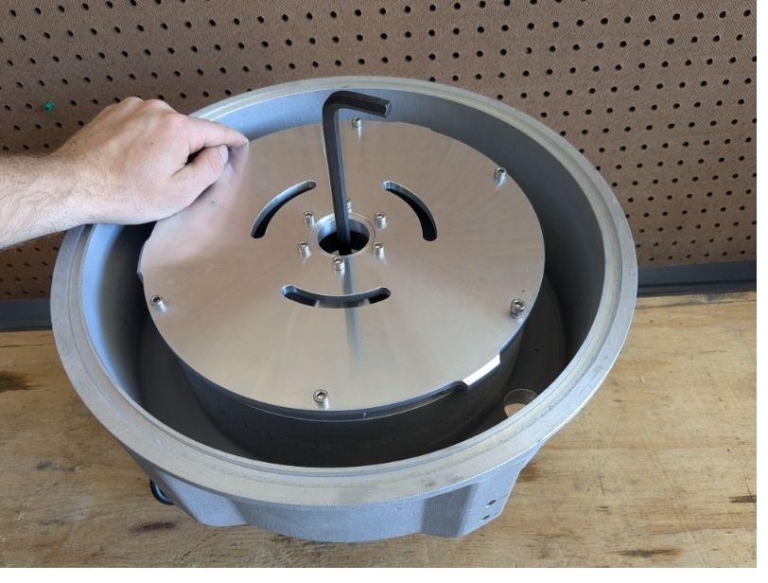
Note: If the bowl does not spin freely or rubs the housing, check that the bowl mount is fully seated and that the bowl is properly centered. Do not operate the centrifuge if the bowl contacts the housing.
Step 8. Attaching Centrifuge Legs
Turning the Ultimate Force onto its side, install each leg with 2 button-head fasteners 11239-19. Hold the top of the leg in place and hand tighten the fasteners with a 6mm Allen wrench. Be careful not to cross-thread the bolts, as the soft aluminum housing threads will strip easily. After installing the first two legs, you can balance the centrifuge on the back legs and install the third leg.
At the bottom of each leg is an included vibration dampener 11239-25 for you to install with bolt 11239-32. Each damper has two holes which are used to mount your centrifuge to a hard surface.
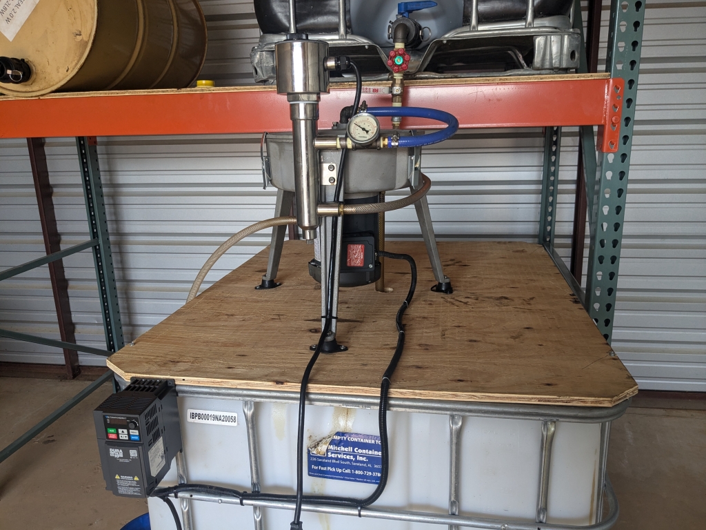
Recommendation: Use a piece of plywood larger than your clean oil container. Mount the plywood to the container, check that the container and plywood will not move, then fasten the centrifuge feet to the plywood.
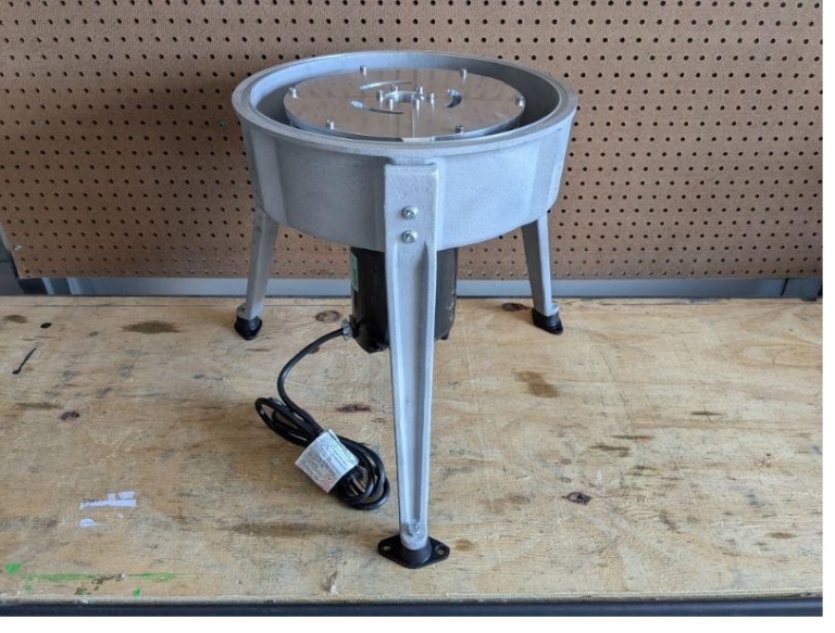
Note: Some vibration is normal during operation — just like a dryer or washing machine. However, excessive shaking may indicate the bowl mount is not fully seated, the bowl is full of debris, or the unit is not bolted to a stable surface.
Step 9. Installing Seals on the Housing and Housing Lid
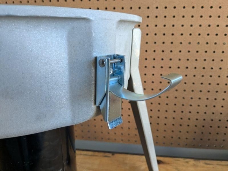
Three latches 11239-08 are used to secure the housing lid. Use a 4mm Allen to install fasteners 11239-20 to the housing. Rotate the centrifuge and install the next latch until all three are installed. Be careful not to cross-thread the fasteners and strip the aluminum threadings.
Place the large housing o-ring 11239-16 into the top groove of the centrifuge housing. Make sure it is not cut or damaged to avoid future leaks.

The housing lid requires two o-rings 11239-12 to be installed in the oil entry inlet. Using a small flat-head screwdriver or the head of a nail, push the o-ring into the inlet until it is fully seated in the groove. Then install the second o-ring using the same procedure in the other groove on the opposite side.

Once the two oil inlet o-rings are installed, fasten the two breather caps 11239-31 in the top of the housing lid.
Place the housing lid on the centrifuge and secure it with the three latches. Holding one side of the lid, tighten the latch on the opposite side — this keeps the lid level so it does not get fastened crooked and leak in operation. The latches are tight but will soften over time. Do not bend the latches or modify them. The centrifuge bowl spins at high RPM and latching the housing tightly is a requirement. Never operate the centrifuge with the housing lid removed.

Note: If the housing lid does not sit flush or a latch won’t close, the seal may be misaligned in the groove. Remove the lid and reseat the seal before forcing anything.
Step 10. Plumbing Parts Assembly Layout
The centrifuge has three plumbing connections for the input and output: one inlet that feeds dirty oil into the center of the bowl, and two drainage ports that handle clean and dirty oil separately.
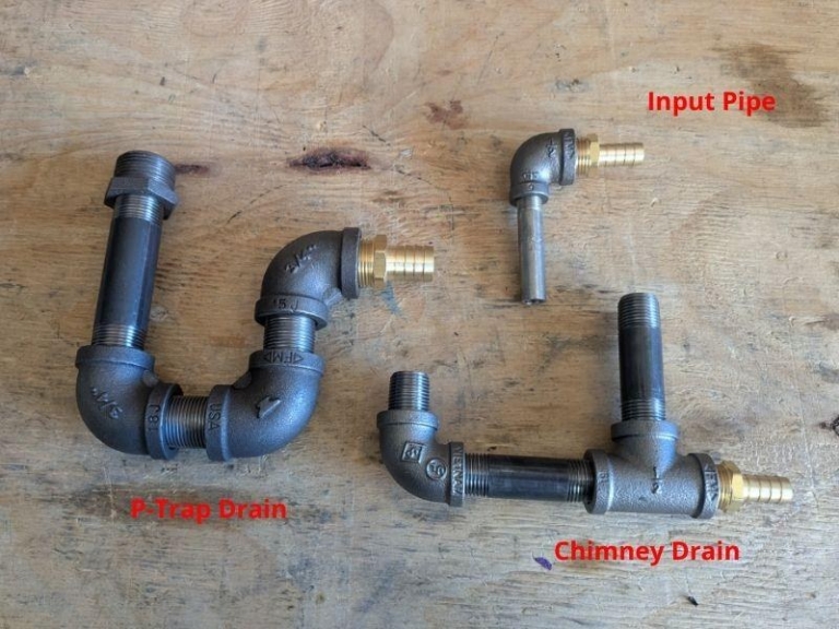
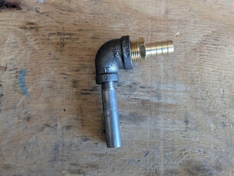
The inlet fitting is comprised of three pieces: the ¼” nipple tube, 90° elbow adapter, and the hose barb. Connect these pieces using Teflon tape and install them into the housing lid — this is a tight fit due to the o-rings and is normal. This inlet fitting will later be connected to the input hose.
Build the drainage fittings directly on the centrifuge, one piece at a time. You cannot pre-assemble the entire fitting and then connect it because the motor will be in the way.
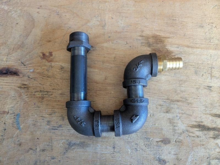
On the clean oil drain, you will install a P-trap. As the centrifuge runs, it pulls air in through the breather caps in the housing lid and pushes that air out through the outlet hoses. The P-trap sits in that airflow path and stops humidity and condensation from getting pushed through into your clean oil container.
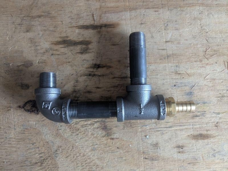
On the dirty oil drain, you will install a chimney “T” fitting. When the inline heater is running, this is where moisture gets forced out of the centrifuge. The P-trap holds it on the clean side, and the chimney exhausts it on the dirty side. Both fittings work together from opposite ends of the system.
You will need to purchase ¾” hose for the clean oil drain and ½” hose for the contaminated oil drain. The length of these hoses is dependent on the distance to your container.
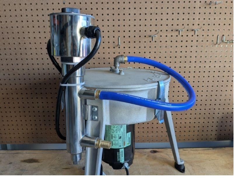
Note: All threaded fittings must be sealed with Teflon tape. Leaks at plumbing connections are almost always caused by missing or insufficient Teflon tape.
Step 11. Setting Up the Heater
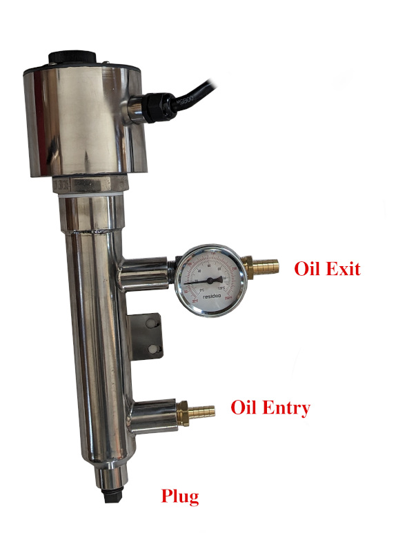
Mount the inline heater to one of the centrifuge legs using the two leg screws. Connect the ¾” hose barb to the bottom of the heater and the ½” hose barb to the top. Install the drain plug in the bottom of the heater.
A hose from your dirty oil container will be connected to the bottom hose barb on the heater. Oil flows from the bottom to the top, keeping the heating element submerged during operation. Run a 400°F rated hose from the top hose barb to the centrifuge lid.
Never use a hose not rated for heat.


Note: Using a hose not rated for 400°F between the heater and centrifuge will cause the hose to melt or fail, potentially spilling hot oil. In addition, running the heater dry (without oil submerging the element) will damage the heating element and may create a fire hazard. Always confirm oil is flowing before turning on the heater.
Congratulations — your Ultimate Force Centrifuge is fully assembled! Continue below to configure your system.
Part 2: System Configuration — “Choose Your Path”
Three-Phase Motor to VFD Wiring (Unleashed VFD Setup)
The Ultimate Force Unleashed comes with a 1/3 HP three-phase IronHorse motor. At 60 Hz this motor runs at its base speed of 3,450 RPM. The VFD increases the Hz, which increases the motor speed — at 88 Hz the bowl hits 5,000 RPM and unleashes 4,950 Gs of force. More G-force means cleaner oil in fewer passes.
The Unleashed ships with an AutomationDirect VFD matched to your voltage. The VFD converts your single-phase wall power into three-phase power the motor requires. The 120V kit uses the GS10 and the 240V kit uses the GS20. Both drives are wired and programmed the same way, with one exception covered below. Always refer to the VFD manual for the most up-to-date wiring instructions and programming.
The single-phase wiring covered in Step 4 does not apply to your Unleashed. Follow this section instead.
Watch the DURApulse GS10 VFD Quick Start video →
Note: Before installing the Unleashed motor, fasten the drainage fitting for the dirty oil drain.

Wiring the Motor to the VFD
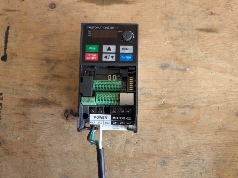
Open the VFD cover to access the wiring panel. The input terminals are on the left side and the output terminals are on the right side. The input terminals are labeled R/L1, S/L2, and T/L3, along with a ground terminal. Your wall power connects directly to these — you do not need a separate fuse or breaker between the wall and VFD.
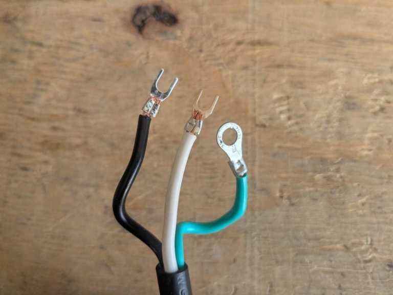
Run your power cord into the drive and fasten 14-16 AWG fork connectors to the cord, then make the following connections:
120V Kit
- Connect the black hot wire to R/L1.
- Connect the white neutral wire to S/L2.
- Connect the green ground wire to the ground terminal.
240V Kit
- Connect the first hot wire to R/L1.
- Connect the second hot wire to S/L2.
- Connect the ground wire to the ground terminal.
In both kits the input is single-phase, so T/L3 is left unused — that is normal.
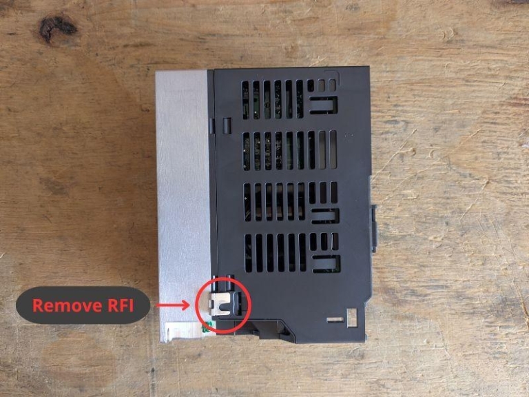
Both drives have an internal RFI jumper inside the wiring compartment near the back. On the GS10 120V kit, remove it. On the GS20 240V kit, leave it in place. The model number on the drive label tells you which kit you have, based on the voltage you selected at checkout.

Note: Removing the RFI jumper on a 240V kit or leaving it installed on a 120V kit can cause drive faults and erratic operation. Check your drive’s model number before you make this decision. If you are unsure which kit you have, stop here and contact AutomationDirect before powering up.
The Unleashed motor can be configured for low voltage (230V) or high voltage (480V). The VFD feeds it 230V power, so set it for the low-voltage 230V configuration. Follow the wiring diagram printed on your motor and group the motor leads as follows:
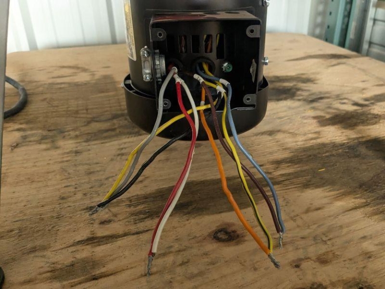
- Join White (T2) and Red (T8) together. This is Line 1.
- Join Blue (T1) and Brown (T7) together. This is Line 2.
- Join Orange (T3) and Yellow/Black (T9) together. This is Line 3.
- Tie off Yellow (T4), Black (T5), and Gray (T6) together and insulate them — these are not connected to anything.
Note: The wiring diagram printed on your motor is the final authority. If the wire colors or terminal numbers on your motor differ from what is listed here, follow the motor.
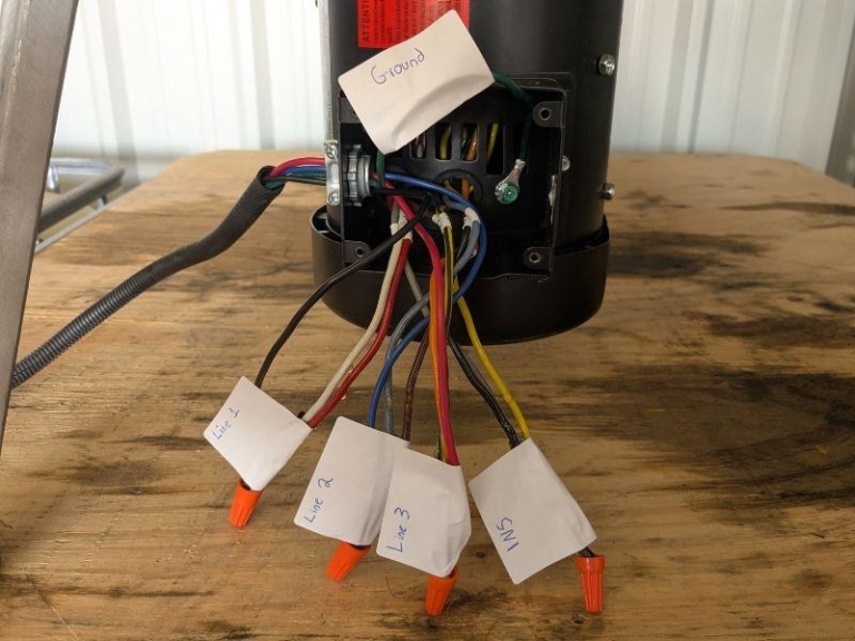
The output terminals on the VFD are labeled U/T1, V/T2, and W/T3. Connect your three motor lines on these terminals and run the motor frame ground to the drive ground terminal:
- Connect Line 1 to U/T1 (Black)
- Connect Line 2 to V/T2 (Blue)
- Connect Line 3 to W/T3 (Red)
- Connect the motor frame ground to the ground terminal (Green)
Make sure to match up the lines from the motor to the correct line on the VFD — Line 1 on the motor connects to T1 on the VFD, and so forth.

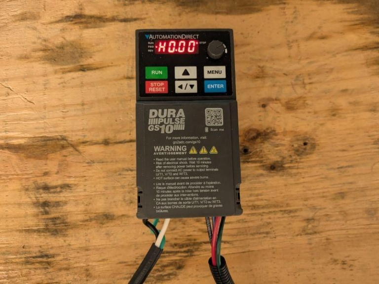
Before you close the cover, check that the terminal screws are tight and both grounds are connected. You can now close the wiring compartment and move on to programming.
Programming the Drive
The GS10 and GS20 are programmed identically. Run through this parameter list regardless of which drive you have. We recommend watching the DURApulse GS10 VFD Quick Start video first before programming the VFD.
The Unleashed ships standard with the 1/3 HP motor. A 1/2 HP motor is occasionally substituted — read the nameplate on your motor before you enter any values to verify its rating. The amp and kW figures differ between the 1/3 HP and 1/2 HP models.
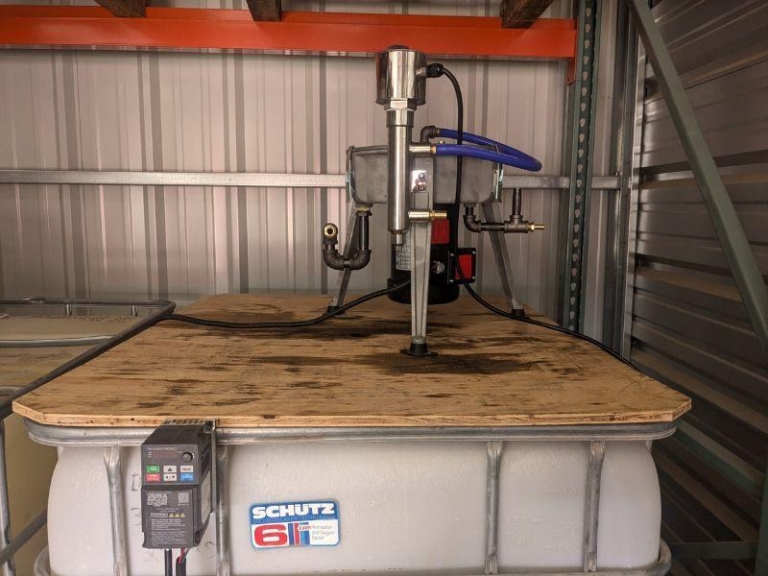
Start by entering the motor’s nameplate values. Set the pole count before the rated RPM — the drive needs the pole count first in order to accept the RPM value.
- Set P05.04 to 2. This is the number of poles.
- Set P05.03 to 3450. This is the rated RPM.
- Set P01.02 to 230. This is the motor’s rated voltage.
- Set P01.01 to 60. This is the base frequency in Hz.
- Set P05.01 to 1.3. This is the full load amps for the 1/3 HP motor. Enter 1.7 for the 1/2 HP motor.
- Set P05.02 to 0.25. This is the rated power in kW for the 1/3 HP motor. Enter 0.37 for the 1/2 HP motor.
Next, raise the frequency ceiling. By default, the drive will not let the motor run past its base frequency of 60 Hz. This setting opens the ceiling so the bowl can reach 5,000 RPM.
Set P01.00 to 90. This is the maximum output frequency in Hz. Your normal running target is 88 Hz and the 90 Hz ceiling gives you a little headroom above that.
Now set the control mode. Standard V/F is all you need for this application.
Set P00.11 to 0. This sets the control mode to V/F.
Set the ramp times. A gentle 15-second ramp up and ramp down brings the heavy bowl to speed smoothly and lets it coast down without a braking resistor.
Set P01.12 to 15. This is the acceleration time in seconds.
Set P01.13 to 15. This is the deceleration time in seconds.
Finally, set up the keypad for start, stop, and speed control. You will operate this drive entirely from the keypad.
Set P00.21 to 0. This sets the run command source to the keypad RUN and STOP buttons.
Set P00.20 to 7. This sets the speed command source to the keypad dial. The up and down arrows also adjust speed.
The drive is now programmed and ready for first startup.
First Startup and Testing
Power up the drive without starting the motor and check the display. If no fault codes appear, continue. If a fault code appears, kill power and recheck your wiring and parameter entries before going any further.
Turn the keypad dial down low to around 5 to 10 Hz, then press RUN. The bowl should begin turning smoothly and quietly — you are confirming that the motor starts and runs without grinding, humming, or hesitating.
Watch which way the bowl is spinning. If it is turning the wrong direction, power the drive all the way down and swap any two of the three motor leads at U/T1, V/T2, and W/T3 — that reverses rotation. Power back up and check again.
Once rotation is correct, slowly bring the speed up toward your running target of 88 Hz. As it ramps up, watch the current reading on the display, listen for any unusual noise or vibration, and check that the motor is running at a normal temperature. If everything stays smooth and steady all the way up, your Unleashed is wired, programmed, and running the way it should.
Note: If the motor hums, will not spin, or throws a fault, kill power immediately and recheck your wiring and your parameter settings. Incorrect wiring or incorrect settings can damage the drive or the motor.
Running Your Unleashed
Because the Unleashed runs through a VFD, you start and stop it differently than the basic single-phase motor. Use the RUN and STOP buttons on the keypad to start and stop the bowl. Set your speed with the keypad dial or the up and down arrows.
Do not start or stop the machine by pulling the plug or cutting power at the outlet. Do not cycle the input power off and on more than once an hour — let the drive do the switching.
If you want to dig deeper into the drive settings, AutomationDirect publishes full user manuals for both the GS10 and GS20 and offers free GSoft2 software for setup and monitoring. You can find both at automationdirect.com.
Watch the VFD wiring and setup video →
Gravity Feeding Setup
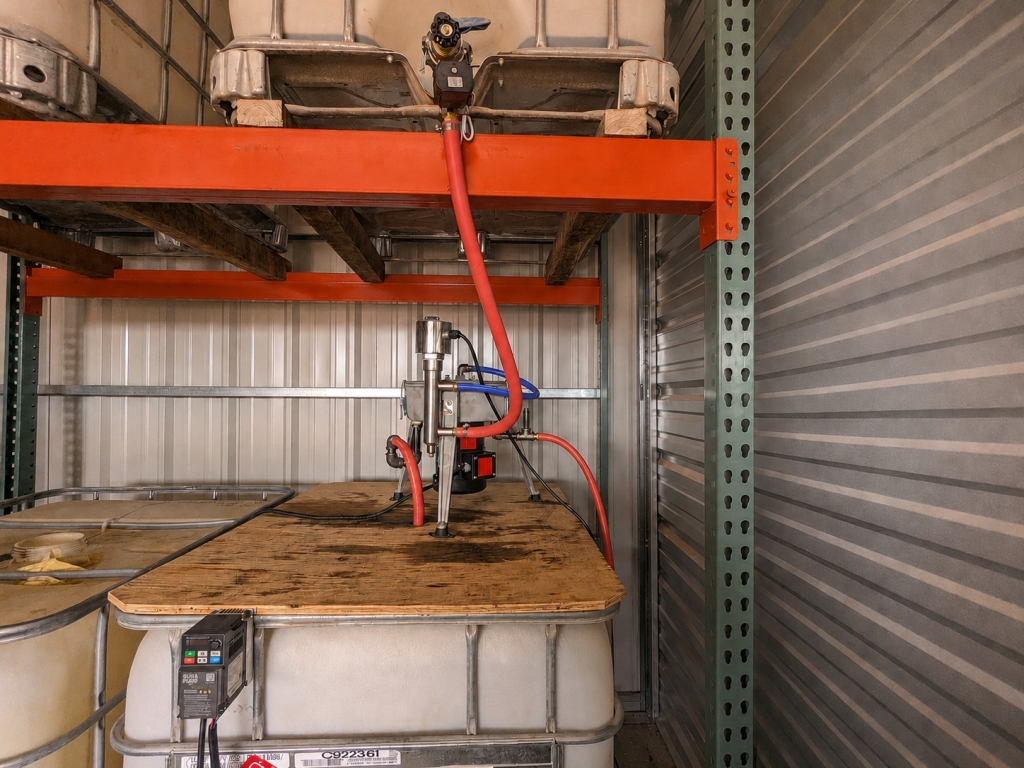
The most common setup for the Ultimate Force Fuel System is a gravity feed system. A dirty container sits on a pallet rack or shelf above the centrifuge. The dirty oil flows to the Ultimate Force Centrifuge, which is sitting on top of the clean oil container. The slower the flow rate, the cleaner the oil will be.
Feeding the centrifuge, we recommend placing the dirty oil container high enough so that you have at least 3 feet from the bottom of the container to the top of the centrifuge. Every foot of elevation will increase psi by 1.2 — the higher you place the dirty oil container, the more steady flow rate will become.
IBC totes or oil drums can be used depending on the amount of space and oil you have available. If you use a sealed oil drum, the dirty oil drum would be placed sideways and adapters connected to the fitting. The ½” port would be highest, used as a vent and refill point.
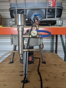
Everyone has different shop space and equipment for building a gravity feed system. Here are some examples from our customers:

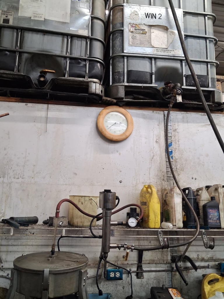
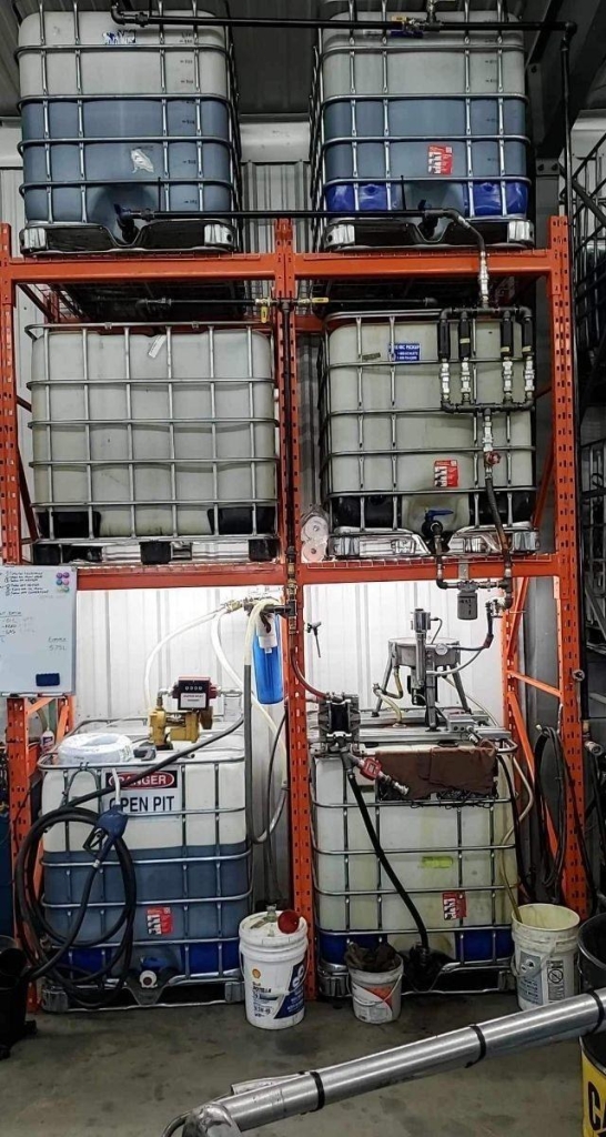

To connect the centrifuge, first assemble the camlock fitting. We use two valves to regulate the flow of oil: a ball valve which is your on/off, and a gate valve which is used to regulate the flow. Once the flow is regulated, you will not need to adjust it any further.

Included in the Gravity Fail Safe Hose Kit, we use an electronic ball valve. This fail-safe valve is connected to the motor of the centrifuge. When the centrifuge is shut off, it automatically closes, stopping the flow of oil.
The valve is 120/240V compatible. Wire the valve by connecting the leads to the hot & neutral wires of your plug, with the centrifuge single-phase motor. The wiring method for the fail-safe valve depends on which motor configuration you have — the standard single-phase motor, or the Unleashed three-phase motor with VFD. Follow only the sub-section that matches your setup.
Once the valve is connected, and the feed hose is connected to the bottom of the inline heater, you can set up the drainage hoses. On the clean oil side, which has the P-trap, use ¾” hosing. For the dirty oil side, use ½” hosing down to the dirty oil container.
Your centrifuge system is now plumbed and ready to purify waste oil. Before you turn the centrifuge on and open the oil supply, make sure both containers on the ground are of equal size or capacity to the dirty oil container. If you have a manual ball valve and forget to close it, or the centrifuge shuts off unexpectedly, there is nothing stopping the oil from continuing to drain out — the dirty oil will fill the bowl, overflow the separation within the housing, and contaminate the clean oil supply.
Note: Always turn the centrifuge ON first before opening the oil flow, and turn the centrifuge OFF last after closing the oil flow. Reversing this order can cause oil to pool in the housing without spinning, leading to leaks and poor separation.
Determining Flow Rate
You don’t need fancy equipment to check your flow rate. All you need is a quart jar and a timer. Time how long it takes to fill your quart jar once, then multiply your target flow rate by 4 (since there are 4 quarts in a gallon), then divide 60 minutes by that number.
For example, if you want 5 GPH: 5 gallons × 4 quarts = 20 quarts per hour. Then 60 minutes ÷ 20 quarts = 3 minutes to fill one quart.
| Time to Fill 1 Quart | Gallons Per Hour (GPH) |
|---|---|
| 6 minutes | 2.5 GPH |
| 3 minutes (Recommended) | 5.0 GPH |
| 2 minutes | 7.5 GPH |
| 1.5 minutes | 10 GPH |
| 1 minute | 15 GPH |
| 30 seconds | 30 GPH |
Note: Running oil too fast through the centrifuge reduces separation quality. If your clean oil appears cloudy, slow the flow rate. Start slow and increase gradually until you find the sweet spot for your oil type and temperature. We recommend a 5 GPH flow rate.
Finishing a Centrifuge Run (Operating Reference)
- Close the oil supply valve (ball valve) to stop oil flow to the centrifuge, or turn off the motor.
- Allow the centrifuge to continue running until the bowl drains (oil stops coming from the dirty oil drain hose).
- Turn off the centrifuge motor.
- Do NOT remove the bowl until all oil has fully drained.
- If cleaning the bowl, follow the Cleaning the Bowl section below.
Cleaning the Bowl
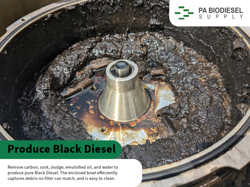
The bowl should be cleaned out every 100 gallons (400 L), or at the end of every batch. At the end of a run, shut off the oil first, then shut off the centrifuge. A half gallon of dirty oil will drain from the bowl into the dirty oil container once it stops spinning. Wait 15 minutes before opening the bowl so that it fully drains.
To remove the bowl, use an 8mm Allen wrench to loosen the retaining nut and remove the bowl from the housing. Use a 4mm Allen wrench to remove the 6 fasteners from the locking lid, turn it clockwise, and lift the lid. The bowl does not need to be removed at every cleaning — you could remove just the lid. Scrape the contaminants out and use a rag to clean up any residual oil. Wipe down the accelerator cone, as you may have sludge and build-up on the cone as well.
Take a fresh bowl liner and cut the ends along the line. Connect the ends of the bowl liner so it forms a ring and place it inside the bowl.
When re-assembling the centrifuge bowl, check that the o-ring is still in place. Tighten the 6 fasteners with a 4mm Allen wrench in a criss-cross pattern and make sure the o-ring is fully seated. Use an 8mm Allen wrench to tighten the bowl nut to the mount inside the housing. You are now ready for the next batch.
Note: Do not use an impact driver or over-tighten the locking screws. Over-torquing will break the steel nut that the screw threads into. Hand-tight with an Allen wrench is sufficient.
Series vs. Parallel Units
For the enthusiast with higher volume fuel needs, it is not uncommon to have two Ultimate Force Centrifuges to double production. There are two methods of setting up these centrifuges — choose whichever fits your needs best.
The first and most common method is a series setup. One centrifuge drains into the second, cleaning the oil twice in a single pass. The advantage of spinning the oil twice is increased debris removal and moisture removal — as the oil passes through the first centrifuge, it is heated and water begins to separate and evaporate. Passing it through a second inline heater increases the temperature again, causing almost all of the water to evaporate out of the chimney fitting on the dirty oil side.
To set up a series centrifuge system, you will need sufficient room between the dirty oil container and the clean oil container. The two centrifuges will be placed at different levels, so that the clean oil exit of the first centrifuge is of enough height to drain into the top of the second centrifuge system. The goal is for gravity to pull the oil through the system, not relying on the low fluctuating pressure of the dirty oil container.
The second method is a parallel centrifuge system. Two Ultimate Force centrifuges pull oil from the same or separate dirty oil containers and operate in conjunction. The clean oil can dump into the same clean oil container or separate containers depending on your needs. This method will double your hourly flow rate and is best for those who just need the oil sufficiently cleaned for older model engines or other purposes. For fuel production in electronic diesel engines 2000+ and newer, we recommend passing the oil twice through a centrifuge system.
Part 3: Reference & Troubleshooting
Troubleshooting / FAQ
My motor won’t start or runs very hot
Check the wiring connections of your motor and verify that it is set up for the right voltage. The motor arrives pre-wired for a 120V configuration. Reference the diagram on the side of the motor for the most accurate details. Make sure the connections are tight and secure, as loose connections will cause the motor to run hot or intermittently.
I have an oil leak from the bottom
There are only two places oil can leak from, not including the drainage fittings: the motor shaft seal and the motor fasteners. Start with the fasteners and use RTV + the bonded washer for a tight seal. If you still experience leaks, check the orientation of the V-seal and make sure the “V” is facing downwards. The motor shaft seal may need replacement or repositioning if damaged during installation.
The top of the centrifuge is leaking
Unlock the three latches and check that the housing o-ring is fully seated. Re-fasten the centrifuge housing lid — hold one side of the lid, and refasten the latch on the opposite side. The lid must be level and centered for it to not leak during operation.
Bowl mount is not fully seated
If the bowl mount is not fully seated or crooked, remove the mount, reheat it in boiling water, and re-install.
I have a vibration on start up and shut down
A small amount of vibration during start up and shut down is normal. Make sure vibration dampeners are fastened to the legs and it is securely mounted to a hard surface.
My centrifuge shakes while operating
Immediately shut off the centrifuge and step away until it is no longer spinning. Remove the bowl with an 8mm Allen wrench. Check that the motor fasteners are not loose — if a bolt is loose, apply lock-tite and RTV. Check the centrifuge bowl and make sure all debris is removed; a full or clogged centrifuge bowl may cause vibration due to uneven distribution of material buildup. Remove the contaminants, wipe the bowl down, and insert a new bowl liner.
My “clean oil” is still dirty
Check that the bowl is not full of contaminants and clean it out. Cleanliness of the oil is determined by the flow rate (speed) of the oil and number of centrifuge passes — debris is separated by mass & weight. We recommend a minimum of two centrifuge passes for most fuel applications. In some instances of extremely dirty oil, additional passes may be required.
Oil is not draining
Check that all feed valves are open, including the IBC tote. If the fail-safe valve is installed (strongly recommended), verify that the valve is properly wired — when connected to power the valve will open, and when it does not have power the valve will close. In some instances, the solenoid may be damaged and the valve will no longer open; replace the fail-safe valve.
My heater is fluctuating
The inline heater has a 32°F safety thermostat. When the heater exceeds the temperature threshold, the heater shuts off and reactivates after it cools. The minimum recommended temperature is 160°F — any rating above this temperature is acceptable.
The bowl screw will not line up
Thread the bowl screw as far as it can go by hand, then give it a ½ turn with a 4mm Allen wrench. Removing the locking lid may be necessary. Using a rubber mallet, gently tap the screw until it is vertical.
The steel press nut fell off
If the steel nut fell off the bowl, it must be reinstalled — do not operate the centrifuge unless all 6 fasteners are in place. Remove the bowl from the housing and remove the locking lid. Place the bowl facedown on a thin piece of cardboard, such as a cereal box. Use a press and push the nut back into place — the bowl must be supported or it will bend and become unbalanced. Reassemble the bowl and check that the fasteners are lined up.
Motor Replacement (Service Reference)
Before disassembling your Ultimate Force Centrifuge, a reseal kit will be needed — this can be found on our website under Ultimate Force Parts. Disassembly will take an hour at most, and you do not want to lose a fastener between disassembly and the time for the reseal kit to arrive.
Using an 8mm Allen wrench, loosen the bowl nut by turning it counterclockwise on the bowl and remove it.
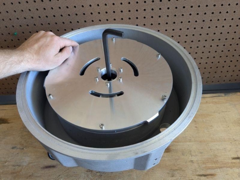
Using a gear puller, attach the three hooks to the bottom of the bowl mount. Hand-tighten the gear puller, then use a wrench to remove the mount from the motor shaft. Ensure the force is applied to the motor shaft, not the housing, allowing the mount to slide off smoothly.

Using a 4mm Allen wrench, remove the legs of the centrifuge, placing the motor base on the ground. Using a 3/16” Allen head screwdriver, remove the 4 bolts securing the motor — set them aside, taking care not to damage the sealed washers. Remove the housing by lifting up from the motor.
Flip the housing upside down and, with a mallet and socket, gently tap out the old seal.
Your unit has now been completely disassembled. Return to the beginning of this guide to reassemble your centrifuge. For a fresh reseal kit, contact us — not stopping a leak will ruin your motor and is unsafe.
Contact
Info@pabiodieselsupply.com
833-370-7590
Quick questions not found in this guide can be answered on our website by Fuel Pal, our AI assistant — trained to answer most questions about the Ultimate Force Fuel System.
Thank you for purchasing from PA Biodiesel Supply! We are so happy to have helped you on this waste oil journey.